Most LED grow lights today either plug straight into a wall outlet or connect to a separate external driver. If yours has a standard plug, you just need to handle the timer, dimmer, or switch wiring between the outlet and the light. If yours uses a bare-wire driver (common with quantum board kits and commercial panels), you wire Line, Neutral, and Ground into the driver's AC input terminals, then run the low-voltage DC output leads to the light board. Either way, the full process takes about 30 to 60 minutes, requires only basic hand tools, and is completely doable if you work carefully and verify each connection before powering on.
How to Wire Grow Lights Safely Step by Step for LEDs

Marcus Tillman
22 May 2026
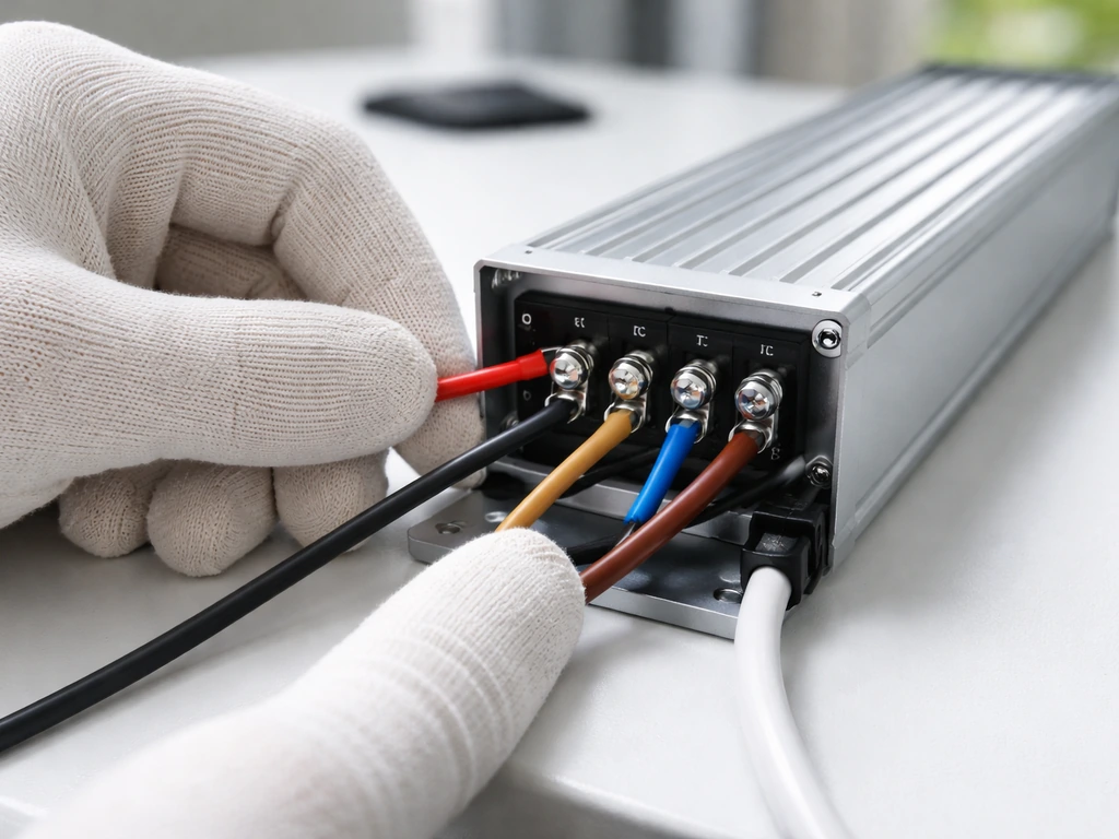
Figure out your grow light type first
Before you touch a single wire, you need to know which wiring scenario you're actually dealing with. LED grow lights fall into two broad categories, and the wiring process is different for each.
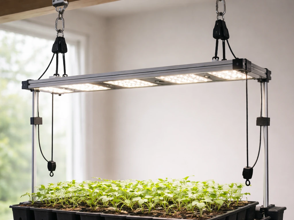
- Plug-in / all-in-one lights: These include brands like Spider Farmer, Mars Hydro, and HLG's ready-to-run units. They come with an attached power cord and a built-in or external inline driver that already converts AC to DC. You plug into a standard 120 V (or 240 V) outlet and you're done with the power side. Your only wiring decisions involve timers, dimmers, or daisy-chain cables.
- Driver-based / DIY / commercial panels: Quantum board kits, COB arrays, and many commercial fixtures separate the driver from the board. The driver (often a Mean Well HLG, XLC, or LPF series unit) needs AC mains wired into its input terminals, and its DC output goes to the LED board. This is real wiring work.
- Hardwired fixtures: Some larger commercial LED bars and horticultural panels are designed to wire directly into a junction box on a dedicated circuit, skipping any plug entirely.
Check your light's documentation right now. If it says 'plug-in' or comes with a cord already attached, you're in scenario one. If it shipped with a separate Mean Well or similar driver box with screw terminals visible, you're in scenario two. If you're installing a large fixture into a grow tent or room without a cord at all, you're in scenario three. The rest of this guide covers all three, so skip to the section that matches your setup.
Tools, parts, and safety before you start
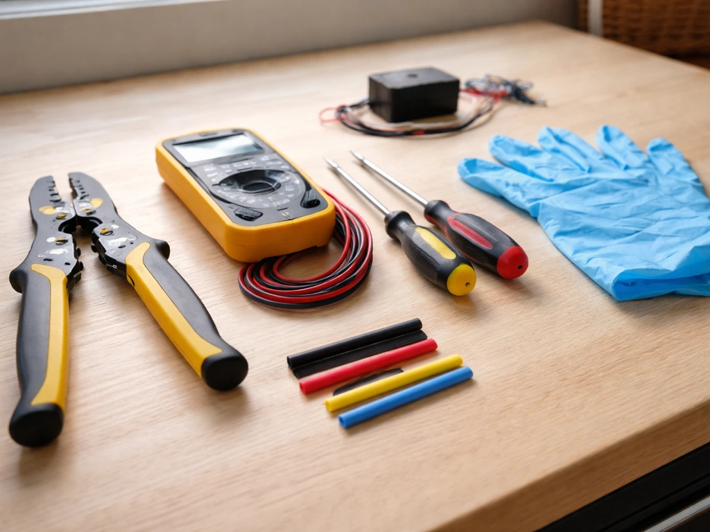
Get everything on this list before you begin. Missing one item mid-job is how mistakes happen.
- Flathead and Phillips screwdrivers (for terminal screws on drivers)
- Wire strippers sized for 14 AWG and 18 AWG wire
- Multimeter (essential for voltage checks and polarity verification)
- Electrical tape and/or heat-shrink tubing
- Wire nuts or lever-type connectors (Wago 221 series are great)
- Strain relief fittings (rubber or nylon cable glands, sized to your cable diameter)
- Zip ties for cable management
- A grounded 3-prong outlet or junction box for the power source
- Your driver's datasheet or installation guide, printed or on your phone
Power safety: the non-negotiables
Always work with the circuit de-energized. Flip the breaker or unplug everything before touching any terminal. LED drivers operate at mains voltage on the input side (120 V or 240 V AC), and that can kill you. The DC output side of a driver is safer but can still cause burns or damage your boards if shorted.
Ground every metal enclosure. If your driver has a green or bare copper ground terminal, use it. Running an ungrounded LED driver in a humid grow tent is a genuinely bad idea. Strain relief is mandatory, not optional: the cable entering any driver or junction box needs a strain relief fitting so that if the cable gets tugged, the pull is absorbed by the fitting and not by the terminal screws inside.
Loose connections caused by missing strain relief are one of the most common causes of flicker and overheating in DIY grow light builds.
A note on electrical codes
In the US, grow light wiring falls under NEC Article 410 (luminaires) and the components themselves should comply with UL 8750, the safety standard for LED equipment. The slide deck “Safety Standards for LED Lighting (UL 8750 overview presentation)” summarizes UL 8750 construction and testing considerations such as [enclosure and openings, bonding, wiring connections, conductor protection, cord strain relief, and security of components](https://www. oas. org/en/sedi/dsd/Energy/Metrology/Documents/Presentaciones/GTEE/9.
%20SICA%20-%20Est%C3%A1ndares%20de%20seguridad%20-%20M. %20Scholand. pdf). The practical takeaway: splices must be in accessible, enclosed wiring compartments (not floating loose), connections to outlet boxes must be secure, and all conductors need proper protection.
If you're hardwiring anything into a circuit panel or sub-panel, get a permit and have it inspected. For plug-in and driver-level work in a grow tent, you're largely doing appliance-level wiring that doesn't require a permit, but the same code principles still reflect good practice.
Understanding your driver's connections
If you're working with a driver-based setup, the driver is the most important component to understand. Mean Well drivers are by far the most common in grow light applications, so I'll use their labeling as the reference point. Your driver will have two distinct wiring zones.
| Terminal Label | What It Is | What Connects Here |
|---|---|---|
| L (Line) | AC mains input, hot/live conductor | Black wire (US) or Brown wire (EU/international) |
| N (Neutral) | AC mains input, neutral conductor | White wire (US) or Blue wire (EU/international) |
| FG or Ground symbol | Protective earth ground | Green/yellow wire or bare copper |
| +V or V+ | DC output positive | Positive lead to LED board (usually red) |
| -V or V- | DC output negative | Negative lead to LED board (usually black) |
| DIM+ / DIM- | Dimming control input (low voltage) | Dimmer signal wires (NOT the -V terminal) |
The AC input side and the DC output side are completely separate circuits inside the driver. Never mix them up. The DIM+ and DIM- terminals are for a separate low-voltage control signal only. Mean Well's own HLG-series datasheet includes an explicit warning: do not connect DIM- to -V. This is one of the most common wiring errors people make, and it can damage the driver or produce unpredictable dimming behavior.
Dimming interfaces: what your driver actually supports
Many Mean Well HLG drivers offer what they call '3-in-1 dimming,' meaning the DIM+ and DIM- terminals can accept three different types of control signals: a 1 to 10 VDC analog signal, a 10 V PWM signal (100 Hz to 3 kHz), or a resistance (potentiometer) wired across the terminals. These are not interchangeable with standard household dimmer switches, which use triac or leading-edge phase cutting. Using the wrong dimmer type on an HLG driver will either not work at all or produce a very narrow, jerky dimming range. Before you buy a dimmer, look up your specific driver model and confirm which dimming interface it supports, then buy a matching 0-10 V controller or appropriate potentiometer.
Step-by-step wiring for the three main setups
Scenario 1: Plug-in light with an inline driver or adapter
This is the easiest setup, and honestly 90% of hobby growers are here. Your light has a cord that ends in either a standard 3-prong plug or a proprietary connector that goes into an inline driver box. The driver box then plugs into the wall.
- Plug the inline driver's input cord into a grounded outlet or power strip. Do not use ungrounded two-prong adapters.
- Connect the driver's output connector to the light fixture's input connector. These are usually barrel connectors or proprietary locking plugs. Match the shapes; they only go one way.
- If your light has a dimmer knob built into the driver, leave it at maximum (100%) for now until you've confirmed the light works.
- If you're adding a plug-in timer between the outlet and the driver, plug the timer into the wall first, then plug the driver into the timer. Confirm the timer is rated for the total wattage of your light (always check the timer's amperage rating: a 300 W light at 120 V draws 2.5 A, so a timer rated for 15 A is plenty).
- Secure any loose cables with zip ties so they don't hang into the canopy or get caught in fans.
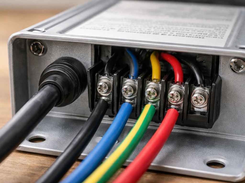
Scenario 2: Bare-wire driver wired to a LED board (DIY / quantum board)
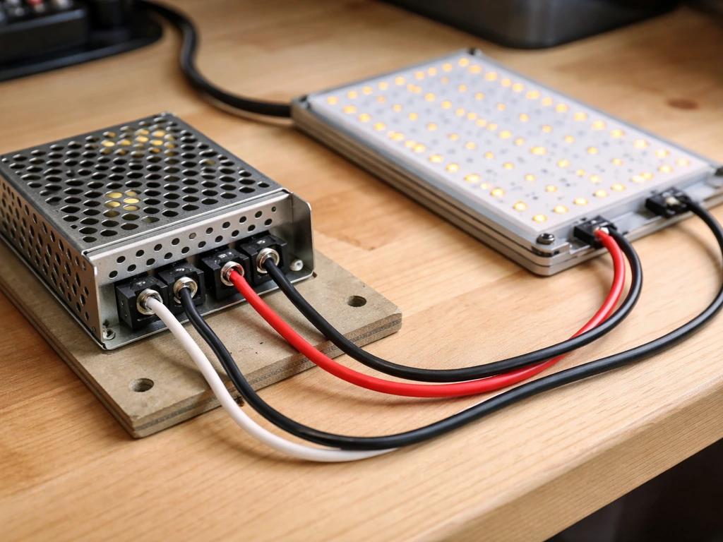
This is the scenario that actually requires wiring. You have a Mean Well or similar driver with screw terminals, and you need to wire AC in and DC out. Work with everything unplugged.
- Mount the driver in a ventilated, non-flammable enclosure or on a metal mounting bracket. Keep it outside the grow tent if possible, since heat and humidity shorten driver life.
- Run your power cable (14 AWG for up to 15 A circuits is fine for most grow lights under 1800 W at 120 V) through a strain relief fitting into the driver's input wiring compartment. Tighten the strain relief so the cable cannot be pulled out by hand.
- Strip about 8 mm of insulation from each conductor end. Connect Line (black/brown) to L, Neutral (white/blue) to N, and Ground (green/yellow or bare) to the FG terminal. Tighten each terminal screw firmly. Give each wire a gentle tug to confirm it's seated.
- Run your DC output cable from the driver's +V and -V terminals to the LED board's input pads or connectors. Match polarity: +V from driver to the positive pad on the board, -V to negative. Red is almost universally positive, black is negative on pre-made harnesses. For barrel connectors, the center tip is positive (+) and the outer ring is negative (-) on standard polarity adapters.
- If your driver has a +V sense and -V sense terminal (some HLG models do), connect these in parallel with the output leads at the board end for better voltage regulation, or short them to +V and -V at the driver if the runs are short (under 3 meters). Check your specific model's datasheet.
- Add a strain relief at the DC output cable entry point to the driver as well.
- Route all cables away from high-heat areas and secure with zip ties. No cable should be touching the LED board's heat sink directly.
Scenario 3: Hardwired fixture into a junction box
Larger commercial grow bars or greenhouse fixtures sometimes hardwire directly into an electrical junction box on a dedicated circuit. This is real electrical work. If you're not comfortable here, hire a licensed electrician for the panel and circuit side. For the fixture connection itself: the fixture's supply conductors (L, N, G) connect to the circuit conductors inside an accessible, listed junction box using wire nuts or listed connectors. Per NEC Article 410 practice, all splices must stay inside that accessible enclosure, not tucked into a wall cavity or hanging loose. The fixture must be secured to the structure, not just dangling from the wire. Use the fixture's built-in strain relief or add a cable clamp at the box knockout.
Adding control: switches, dimmers, and timers
Getting your light on a schedule and at the right intensity matters as much as the wiring itself. Here's how to set up the most common control scenarios for LED grow lights. If you want adjustable grow light intensity, choose a driver and dimmer setup that supports the dimming type your driver expects adjustable grow lights.
Plug-in mechanical or digital timers
For most home growers, a plug-in mechanical or digital outlet timer is the simplest and most reliable option. Plug the timer into the wall, then plug your light's driver into the timer. Set your photoperiod: 18 hours on / 6 hours off for vegetative growth, or 12 hours on / 12 hours off for flowering. Make sure the timer's amperage rating exceeds your light's draw with some headroom. A 1000 W fixture at 120 V draws about 8.3 A, so use a timer rated for at least 10 A, preferably 15 A.
0-10V dimmers for driver-based lights
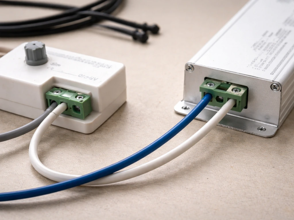
If your driver supports 0-10 V dimming (check the label or datasheet for '0-10 V' or '1-10 V'), you connect a compatible 0-10 V dimmer to the driver's DIM+ and DIM- terminals using a separate low-voltage wire pair.
For the MD-012-180VTD52JV2 Triac/0-10V dimmable LED driver, the installation guide specifies connecting a 0-10V dimmer to the driver's designated 0-10V dimming wires (grey and purple), as shown in its 0-10V dimming diagram connect a compatible 0-10 V dimmer to the driver's DIM+ and DIM- terminals.
This control wiring is completely separate from the AC mains wiring. The AC power goes to L and N as normal; the dimmer just sends a small DC voltage signal (0 to 10 V) to the DIM terminals to set brightness. At 10 V signal, the driver runs at full output. At 1 V (the floor for 1-10 V systems), it's at minimum brightness.
At 0 V, many drivers shut off entirely. Wire gauge for dimming leads can be as light as 22 AWG since there's virtually no current flowing through them.
Resistance (potentiometer) dimming
Some Mean Well HLG drivers come with a small potentiometer wired across DIM+ and DIM- at the factory, or accept one you add yourself. This is the simplest dimming method: you're just varying resistance (typically 0 to 100k ohms) to control output. It's not compatible with 0-10 V wall dimmers or PWM controllers. If you're using a driver's built-in trim pot, leave it alone unless you need to dial in a specific output level.
Inline switches
If you just want a simple on/off switch in the AC line (no dimming), use an in-line switch rated for the full load. Wire it into the Line conductor only, never the neutral. In a junction-box setup, a properly rated wall switch on a dedicated grow room circuit works perfectly.
Test everything before you mount the light
Do not mount your light to the ceiling or tent bar before you've confirmed it works correctly at bench level. This saves you a huge amount of frustration. Here's the verification sequence.
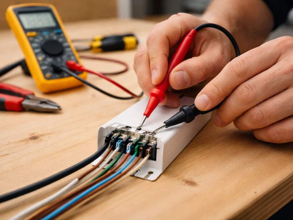
- Visual inspection first: Look at every terminal in the driver. No bare copper should be exposed outside a terminal. No wire insulation should be caught under a terminal screw. Ground is connected. Strain relief is tight.
- Check polarity on DC output before connecting to the board: Use your multimeter set to DC voltage across the +V and -V output terminals of the powered driver (with nothing connected to the output yet). You should read the driver's rated output voltage, for example 24 V, 36 V, or 48 V depending on your model. The red probe on +V should give a positive reading. If you get a negative reading, you've swapped polarity somewhere.
- Connect the LED board and power on: The board should illuminate fully, evenly, with no flickering. A steady, full-brightness light with no buzzing or flickering is 'good.'
- Check operating temperature after 5 minutes: The driver case may be warm but should not be too hot to touch briefly (under 60 degrees C is generally fine). The LED board's heat sink should be warm but not burning. If either is painfully hot within 5 minutes, something is wrong.
- Test dimming if applicable: Rotate the potentiometer or adjust the 0-10 V dimmer from minimum to maximum. You should see smooth, gradual brightness change across the range. If the light jumps abruptly, won't dim below 50%, or flickers during dimming, the dimmer type is likely mismatched with the driver's dimming interface.
- Confirm timer function: Set your timer to cycle on and off a few times while watching the light. Confirm it switches cleanly with no arc flash visible at the outlet or buzzing from the driver.
Fixing the most common wiring problems
Light won't turn on at all
Start with the basics: is the outlet live? Plug a phone charger into the same outlet to confirm. Check that your timer is in its 'on' window if one is in line. On a driver-based setup, use your multimeter to check for AC voltage at the driver's L and N input terminals (with the power on briefly and carefully).
If you have input voltage but no DC output, the driver may have blown a protection fuse internally, or you may have wired L and N correctly but have a broken ground causing the driver's protection circuit to shut down. Also check that your DC output leads are fully seated in their terminals. A loose strand that didn't fully make contact is extremely common.
Flickering
Flickering almost always means a loose connection or a mismatched dimmer. Check every terminal screw in the driver and tug each wire gently. If it flickers only when the cable moves, you have a bad connection. Re-strip and re-terminate that conductor. If it flickers at a specific dimmer setting, your dimmer is likely using triac (phase-cut) dimming on a driver that expects 0-10 V or PWM. Replace the dimmer with a compatible type.
Dimmer not working or only dimming a tiny range
This is almost always a dimmer compatibility issue. Mean Well HLG drivers using '3-in-1' dimming accept 1-10 VDC, 10 V PWM, or resistance, but standard wall dimmers and many cheap LED dimmers use triac phase-cutting, which is completely incompatible. If your dimmer only gives you a narrow range (say 70% to 100%) or does nothing at all, buy a dedicated 0-10 V analog dimmer or a PWM controller that matches your driver's spec. Also confirm you haven't accidentally connected DIM- to -V on a Mean Well driver; that's specifically flagged in Mean Well's documentation as something that breaks dimming behavior.
Driver or board overheating
If the driver is running extremely hot (too hot to hold your hand on), first check that it has adequate airflow around it. Mean Well drivers need at least a couple of centimeters of clearance on all sides and do not belong in sealed boxes without ventilation. If airflow is fine but it's still running very hot, verify that you haven't connected a light that draws more wattage than the driver's rated output.
Running a driver at 100% of its capacity continuously shortens its life significantly. Size your driver at 80% of its maximum output or less for long-term reliability. For LED board overheating, confirm the board is properly mounted to its heat sink with thermal interface material between the two.
Incorrect output voltage
If your multimeter reads the wrong voltage at the DC output (for example, 12 V instead of 24 V), check whether your driver has a voltage adjustment trim pot and whether it's been accidentally turned. Also verify the driver model matches what the LED board requires. Connecting a 48 V driver to a board designed for 24 V is a fast way to destroy the board.
Where to go from here
Once your light is wired, tested, and confirmed working, mount it at the correct starting height for your plants and set your timer schedule. For practical rules on when to raise the lamp as your plants develop, see click and grow when to raise light. The height question matters a lot because LED grow lights, even well-wired ones, can bleach or stress plants if hung too close.
If you want more precise guidance, see our step-by-step tips on how to adjust grow light height for different growth stages. Seedlings generally need lights much higher than established vegetative plants, and you'll adjust height frequently as plants grow. If you also want to raise and lower grow lights as your plants develop, you can use the same height and intensity principles discussed in the next placement section.
For adjustable grow lights, you typically combine the driver’s dimming controls with a way to set and maintain the light height over time. If you want to raise and lower grow lights over time, pair the dimming or control strategy with a height adjustment plan that keeps intensity consistent as plants grow how to raise and lower grow lights. Getting your wiring sorted is step one; optimizing placement, intensity, and schedule is the ongoing work that actually drives results in your grow.
FAQ
Can I splice into a pre-made LED grow light cord to change the length or add a plug?
If your LED grow light came with a plug already attached, do not open the plug or splice conductors inside the cord. For plug-in setups, the “wiring” you do is only the connection between the plug (or inline driver box) and your timer or switch, and the timer or switch must be rated for the light’s full draw (plus headroom).
If I want an on/off switch, should I wire it to Line, Neutral, or Ground?
For grow lights, a switch on the Line conductor is the safe default, because it breaks the hot feed to the driver. Neutral should not be switched in normal installations, especially if the driver expects neutral to remain referenced properly for its protection circuitry.
How do I confirm the driver voltage is compatible before powering anything?
Use the driver’s model label to find the correct input voltage range, then confirm your wall supply matches it (for example 120 V vs 240 V AC). Also verify the DC output spec (voltage and current range) matches the LED board, because a mismatched DC voltage can fail the board even if the driver turns on.
Can I extend the dimming wires or move the dimmer further away from the driver?
Yes, but only on the correct side of the driver. Splicing or disconnecting the low-voltage DIM+ and DIM- leads is usually low risk electrically, while messing with L, N, or Ground while energized is dangerous. If you need to extend dimming wires, keep the low-voltage pair together and use proper strain relief and an enclosed junction, not a taped splice.
Why does my light flicker or dim only slightly when using a normal wall dimmer?
Do not use a typical household triac dimmer with most Mean Well HLG “3-in-1” drivers unless you specifically know it outputs 0-10 V or PWM to the DIM terminals. A mismatch commonly shows up as no dimming, flicker at certain settings, or only a tiny brightness range.
What happens if I leave the DIM terminals disconnected?
If your dimming control doesn’t include DIM wiring at all, leave the DIM terminals alone rather than guessing. Some drivers will run full output with DIM open, but others may default differently depending on the driver design. The safest approach is to follow the driver’s terminal labeling exactly and confirm the intended “default” behavior in the documentation for that model.
What should I check if the driver runs extremely hot even though wiring is correct?
Thermal protection issues are often caused by missing ventilation or too-tight mounting. Confirm there is airflow around the driver (open sides, not sealed into plastic or foam), and ensure the driver wattage is not pushed continuously at its maximum rating. If the driver is hot even with airflow, also check LED board mounting and thermal interface material between the board and heat sink.
My multimeter shows a different DC output voltage than expected. Can I just adjust the trim pot?
Some drivers include a voltage adjustment trim pot or a factory-set output level. If you measure the DC side with the correct meter range and see unexpected voltage, don’t just force it higher. Reset to the manufacturer’s expected setting range, and verify the LED board’s rated voltage before making further changes.
Can I use one driver to power multiple LED boards?
Yes, but only when you do it correctly for the driver. Confirm the driver output type (constant voltage vs constant current, and the voltage range it supports). Then mount and wire the driver and board according to the driver’s output terminals and polarity requirements, and secure all connections so they cannot loosen from tent movement.
What’s the most common DIY wiring mistake that leads to flicker or overheating?
Rule of thumb: place and secure splices inside accessible enclosures, use listed connectors or wire nuts, and never rely on a twist-and-tape connection for mains wiring. Also ensure cables are clamped to strain relief fittings so tugging stress does not transfer to terminal screws inside the driver or junction box.
If I accidentally swap Line and Neutral on the driver input, will anything break?
If L and N are swapped, many drivers still start, but protection behavior and certain circuit faults can be unpredictable, especially for setups that include dimming electronics and grounded enclosures. The practical recommendation is to match L to Line and N to Neutral as labeled, then verify Ground continuity to all metal parts.
What is a safe “bench test” procedure for newly wired grow lights?
To test safely, energize briefly with the fixture mounted in a stable position, then re-check seating and connection tightness once power is off. Use only insulated meter probes, avoid touching metal enclosures or exposed conductors, and do not leave the system running unsupervised until you confirm stable behavior over a few on/off cycles.
Can I combine a timer and dimming, and what’s the best way to do it?
Driver dimming is separate from plant lighting schedules. If you use a timer for on/off, use the timer for photoperiod and keep dimming for intensity adjustments only. For example, it is usually better to run “on” for the full photoperiod and apply dimming within that window, rather than turning on/off rapidly or combining incompatible dimmers that cause flicker.
Next Article
How to Make Adjustable Grow Lights: Build and Set Height
Step-by-step guide to build adjustable grow lights with safe mounting, height calculations, and canopy distance tuning.